Advice needed on adding external codec

So here it is so far, and mostly successful!

Here is the diagram:

And here is the code for it:

Here are some examples of the output. Here is the code for outputting a tone:

And here is a video of the result:

Someone mentioned about the long wires to the SAI causing a problem. As you can see, as I move the wires, it causes interreference. I wasn’t expecting this kind of interreference with digital signals, but I guess it is the ground side?

Here is the code for just sending a signal received by one codec and sending it to the output of the other:

Here is a video of the internal codec receiving a signal and sending it out of the external one:

This sounds OK.

Here is the external codec receiving the signal and sending out of the internal one. It is much noisier:

So I’m hoping if I do this all on one board with short traces then it will not have the noise issues? Is there anything else I can do to reduce noise issues? Choice of resistors or capacitors? separating analogue and digital ground? moving some components around? As I’ve mentioned before, I’m not an electronic engineer, just someone who can follow a schematic.

3 Likes

Hi Paul!
Thank you for the wait.

It’s really awesome to see this update!!

As for troubleshooting the noise, we definitely recommend starting with shorter wires! Longer wires are going to act more like an antenna and pick up interference from the environment, or the other wires as you move them around relative to each other. That should all be fixed by moving to a board with short traces.

Keep us updated for sure! This is a really cool project :slight_smile:
Let us know if you have any other questions.

1 Like

Really cool stuff @pauldee!

@Takumi_Ogata, will you also be providing the info needed to connect an addition pcm3060? Since the WM8731 is EOL, I would much rather use the pcm3060 for my project.

Thanks!!

2 Likes

Thank you for your response. I figured that was the issue. It’s not such a big deal as this is a development kit for sandboxing ideas, but on a finished project it will be on one board, and I will definitely keep the traces short.

1 Like

Yes and for me it will be good to have another option codecs.

The SAI should be used in a very similar way for these codecs, so I think you should be able to reference the Patch schematic and also datasheet.

@pauldee, did this end up being the case with WM8731?

Still no reference schematic for Seed with pcm3060 - should it use the same cap and resistors on the audio out as the earlier board?

I mostly followed the Seed v5 schematic, but I did refer to the Patch schematic, v4 I think? With the original codec.

Hello Paul! I’m sorry for the delay. The Seed Rev7 schematic is now live on the product page.

Thank you for the wait!

Thank you, I’ll take a look!

Hi, that seems to be a reduced version - it doesn’t have the codec on there?
Also I see you have removed the field schematic? Will it be back at some point please?

I overlooked that it didn’t include a detail about the codec. I’m sorry about that.
I asked the team about this and they told me that they’re working on a new datasheet that will have a typical app circuit for adding second audio codec. I hope that it will answer any questions that you have.

And my guess is that we’re currently migrating the schematics from the github repo to the product page.

Cheers. The open source hardware is a big draw of the platform so I hope you stick with the policy!

The hardware is not open source, and never was.

Oh I see, does that mean you won’t be making it available again?

All boards which are not the Daisy Seed are open source hardware, so the design files will be available again.
Currently, we are still in a middle of adding all of the design files for some of the breakout products to their associated product pages on our website.

We greatly appreciate your waiting. Thank you.

Thank you @Takumi_Ogata!

1 Like

Hi, I’m looking at adding a similar external codec unit for the PCM3060 but have a question: VCOM on the PCM3060 is connected to CODEC_2_VCOM, but I’m not sure what this is? I can’t seem to find any reference to it anywhere else?

I’m really sorry for the delay in response.
VCOM is generated by the codec as a reference voltage. It’s VCC / 2, so in this case 2.5V.
This post explains it well: voltage reference - Why is the Vref of the DAC used in the op-amp amplifier stage? - Electrical Engineering Stack Exchange.

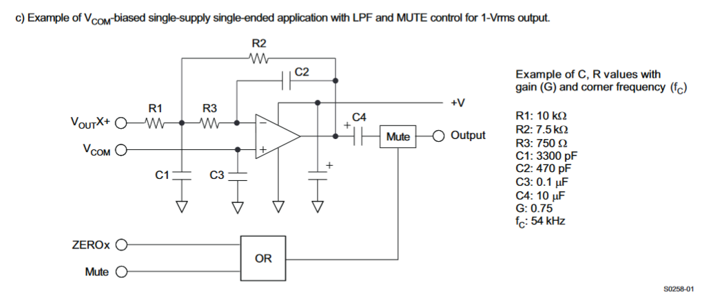
I’ve also attached a reference circuit from the PCM3060 datasheet that uses it.

1 Like

Thank you, that is helpful.

1 Like