Hi,
Basic query here. Im wanting to add a 3 way selector switch to a seed to switch between three digital options.
Questions:
-
Am I correct that I have to use a DP on-on-on switch or can I use an DP on-off-on or can i get away with a SPDT?
-
Do I have to use at least two GPIO pins on the seed or is there a trick whereby I can only use one by say limiting the current on two of the pins?
-
If using two GPIO pins from the seed and a DPDT on-on-on I would assume Id have to code a small conditional that for example says
if((in1 == 0)&&(in2 == 0))
{out1 = x;
}
else if((in1 != 0)&&(in2 == 0))
{out1 = y;
}
else if((in1 != 0)&&(in2 != 0))
{out1 = z;
}
Example wiring
Is this correct?
Thanks
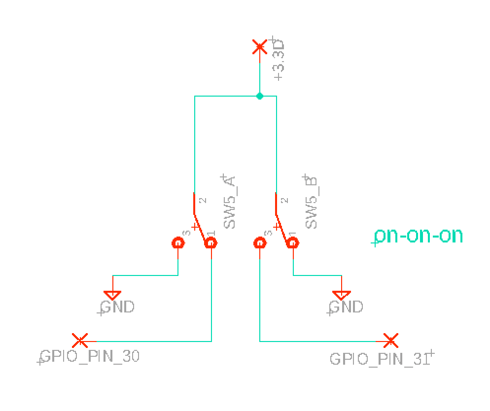
As mentioned in the seed datasheet, grounding a digital pin that is set up as a switch is all that is needed to register an on event.
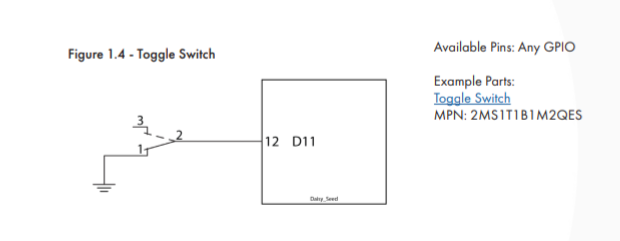
The way I have set up my on-off-on toggle with two digital pins is by connecting the common pin (2) to ground, and the two other pins (1 and 3) to their own respective digital pin. This way one, the other, or neither pins are grounded in the 3 different switch positions.
1 Like
Thanks NVP,
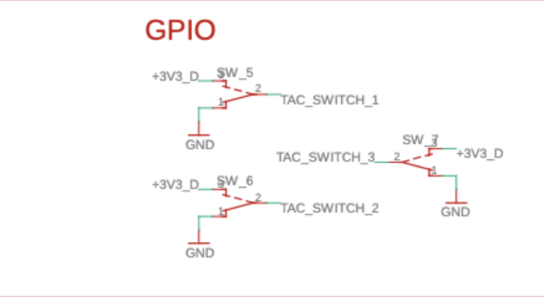
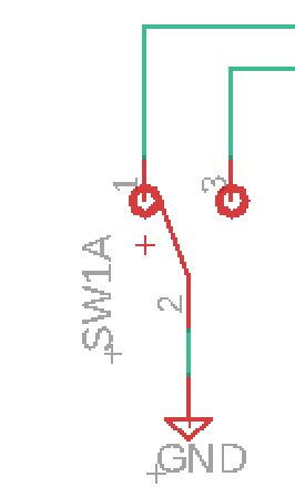
I got a little confused referencing the Petal’s use of GPIO switch that also integrated the +3V3_D line. What is the difference between this and the simple GND version you supplied?
I believe the simple switch to ground works because the pin has an onboard pull up resistor that brings the pin back up to 3v3 when not being pulled to ground. That schematic is doing it manually, pulling the pin up to 3.3v or grounding it depending on position. I haven’t been able to find much clear information about pull up resistors on daisy gpio, but their suggested switch connections in the datasheet document suggests they are present, so I’m not sure why the petal does this.
1 Like
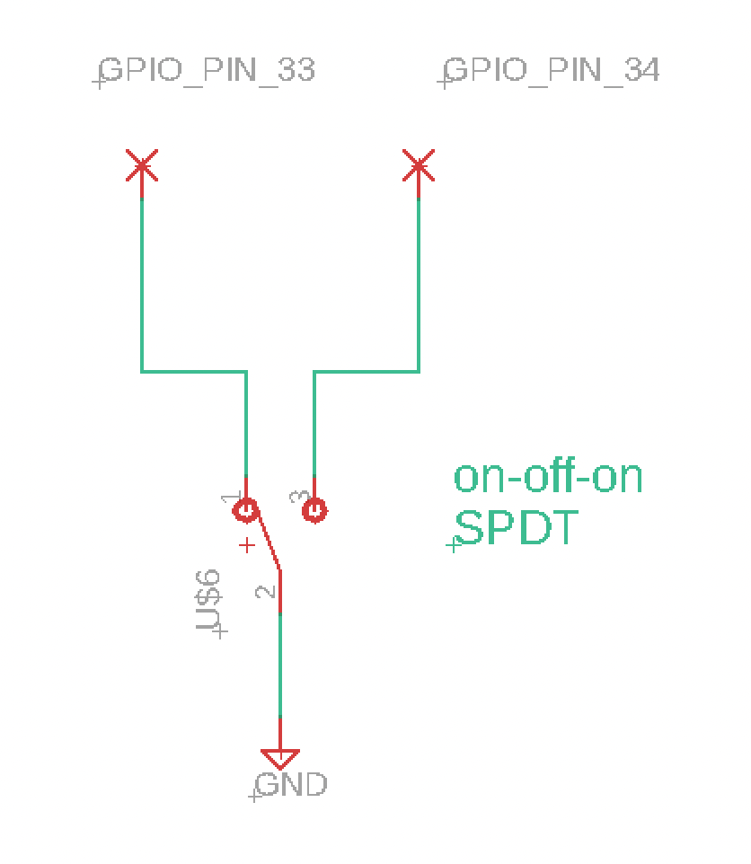
It can be done with one SPDT ON-OFF-ON, a few resistors, and an analog port.
The libDaisy Switch3 class can be used for this in software, and expects a SPDT on-off-on switch, with the middle terminal connected to GND, and the other two terminals connected to unique GPIO inputs.
You initialize the Switch3 class with both GPIO, and under the hood it configures them each as inputs with built-in pull up resistors. So all you need is the toggle and some wires.
The Read function will then return the position of the switch.
Hope that helps!
3 Likes
Thanks Stephen,
Im doing this in Max MSP via oopsy.
Would a simple contitional ‘watcher’ still work with the STDT on-off-on swtich?
Many thanks,
adrian
(I would breadboard this at work to test but im stuck at home isolating and making updates for a new PCB design to send off this week)
if((pin33 == 0)&&(pin34 == 0))
{out1 = 0;
}
else if((pin33 != 0)&&(pin34 == 0))
{out1 = 1;
}
else if((pin33 == 0)&&(pin34 != 0))
{out1 = 2;
}
Hi Adrian, that should work. It can probably be simplified since mechanically only one of the pins can be pulled low at a time.
if (pin33 == 0)
  out1 = 0; // one side
else if (pin34 == 0)
  out1 = 1; // other side
else
  out1 = 2; // middle
2 Likes
Thanks Stephen.
Appreciate the quick response 
Out of interest would you be able to explain the snipped above from Petal that has a +3.3vD line attached to the switch and in what instance one may want to implement it as compared to Switch to GND?
Thanks
The toggles on the petal don’t require the internal pullup resistor. The input can be configured with pullup, pulldown, or no pull, and still function because the external hardware is setting the state of the pin in each position.
Connecting the Toggle to GND only is usually simplest because there is already a ground plane on the board, and it doesn’t require any additional routing or components. You could even do the opposite, connecting one leg to 3v3, and floating the other while using the pulldown configuration instead.
Generally, it comes down to preference.
1 Like
HI,
I’m going to need some more help implementing “Switch3” in Oopsy and the JSON file.
Im wanting to use a “on off on” SPDT switch to control a ‘selector’ as seen below.
NOTE - I previously have had the SPST switch working but have now need to introduce a 3 way option switch.
My oopsy custom JSON file looks like this:
{
“name”:“switch_Test”,
“defines”: {
“OOPSY_TARGET_HAS_MIDI_INPUT”: 1
},
“components”: {
“sw1”: {
“component”: “Switch3”,
“pin”: {
“a”: 28,
“b”: 27
}
},
“aliases”: {
“sw1”: “sw1”,
}
}
The physical switch is as below with the centre pin tied to GND and the outside arms tied to GPIO pins 27 and 28.
Questions:
-
Within Max I am correct in just using a Param called ‘sw1’ with a value between 1 and 3 for this?
-
When I use “Switch3” in this way I get no Control output. If I use my old way of having two ‘on/off’ switches tied together in Max and using a expression to sence the state It kind of works but I can only ever get two options out, not 3.
Thanks in advance for your help
AD
Testing this with the Dev branch of Oopsy, I think is showing a bug with the Switch3 component interpretation in the custom JSON file.
Basically when I ‘make project’ with the Dev version and have switch3 setup in the custom JSON file I get no switch action at all.
The resulting .cpp file shows the switch3 components as :
		sw3.Init(seed.GetPin(10), seed.AudioCallbackRate(), daisy::Switch::TYPE_MOMENTARY, daisy::Switch::POLARITY_INVERTED, daisy::Switch::PULL_UP);

		sw5.Init(seed.GetPin(28), seed.GetPin(27));
		sw4.Init(seed.GetPin(26), seed.GetPin(25));
This is the JSON File Snippet. Sw3 is a momentary switch. sw4 and sw5 are SPDT 3 way switches.
"sw3": {
			"component": "Switch",
			"pin": 10
		},
		"sw5": {
			"component": "Switch3",
			"pin": {
				"a": 28,
				"b": 27
				}
		},
		"sw4": {
			"component": "Switch3",
			"pin": {
				"a": 26,
				"b": 25
				}
		},
AD
I worked it out using the standard “switch” component for the Custom JSON.
The problem was I was being too tricky in the CodeBox operator. As seen in the previous post I was creating a variable called “shape” and sending the result of that to the output. This for some reason was failing so I just used the old ‘in1’ and ‘out1’ and it worked.

AD
1 Like
Can you explain this in detail?
The problem was I was being too tricky in the CodeBox operator. As seen in the previous post I was creating a variable called “shape” and sending the result of that to the output. This for some reason was failing so I just used the old ‘in1’ and ‘out1’ and
I meant that within the codebox the result work if I didnt initiate a variable called shape.
Instead it would read:
if(in1 == 0){
 out1 = 1;}
elseif (in2 == 0){
 out1 = 3;}
else(out1 = 2;
}
Hey there,
If it wouldn’t be too much to ask, how did you go about linking pins A and B inside of gen~? I’ve been trying for the last week to get it to work with the FunBox pedal and can’t seem to figure it out. Any help would be greatly appreciated!
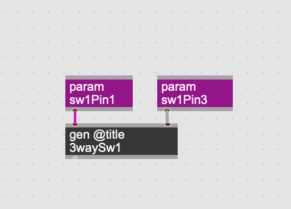
Hi Zac,
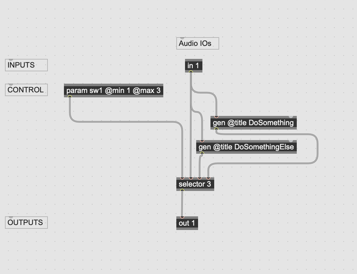
Im now using a simple gen ‘switch’ as Illustrated below.
The two physical inputs (mapped via the Json File) feed a gen object as params.
The Gen object simply outputs whatever you wish, in my case 1, 2 or 3 depending on the physical switch position.
Does that make sense?
Ade
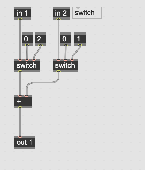
Hmm, doesn’t that output 0,1 or 2?
Oops, Nevermind.
Here’s the silly little way I’m handling three way toggles in gen~
My Json is set to recognize each ‘on’ in a 3 way toggle as its own switch, middle position being ‘default’.
FunBox.txt (1.9 KB)
Thank you for all the suggestions, I really appreciate it! I must have something wrong with my .json file because I can still only get positions 1 and 3 to register for some reason. I’ve attached what I’ve got thus far. What do your .json files consist of when it comes to this part of the file?