Hi all,
I got distracted with other projects and just got back to Daisy. I designed a PCB based upon the Patch schematics and before I send it out to fab, wanted to double check things.
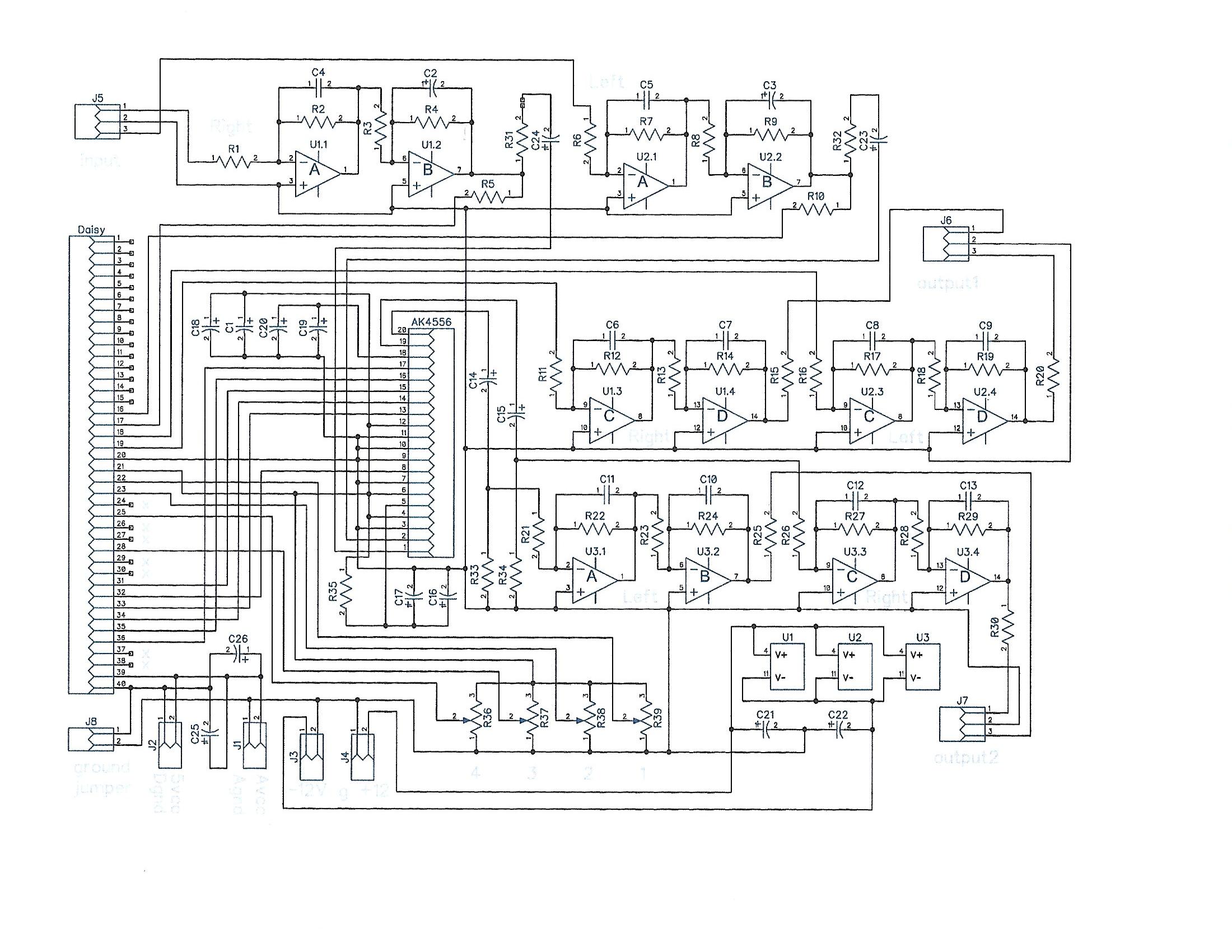
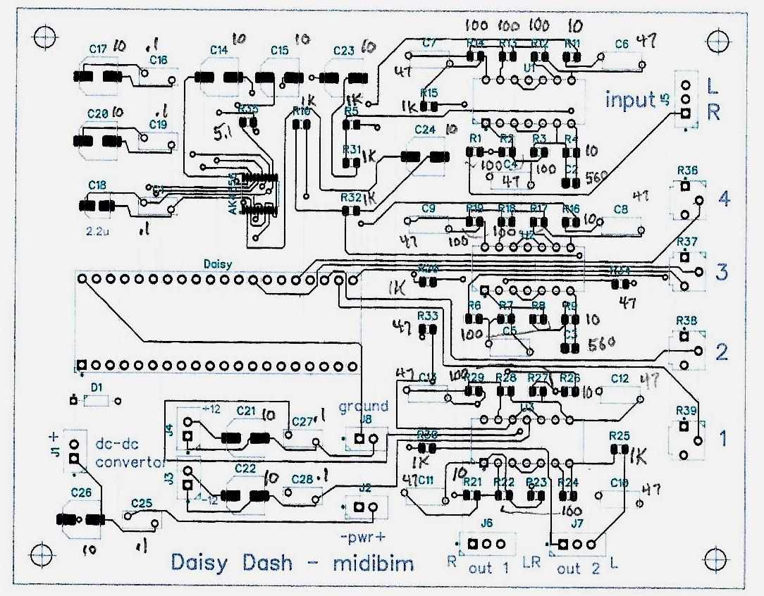
- R19 5R1 resistor on the codec - what’s that for? Should be 5% is OK?
- Daisy pin 21 - this is the output of the Daisy’s onboard 3.3V regulator, right?
because I want to use this power for the pots and one AK4556 (I have a couple)
- 10uF filter going into and coming out of the AK4556, should be + on the codec side?
I would share the schematic if anyone is interested. It has a stereo input but four audio outputs. It uses +5 volt power and there is a DC-DC convertor module for the three TL074. There is a two pin header to connect the two grounds together.
thanks - PJ
The AK4556 data sheet (22 page version at https://upverter.com/datasheet/ae3c782f80d262f78bae1b98785ec24c3267bc44.pdf ) on page 19 has what I think is the same, and probably the origin of, Daisy’s circuit. It does show the polarity of the electrolytic caps. It doesn’t specify any special characteristics for the 5.1 ohm resistor so I think you’d be safe with 5 percent.
I’d be very interested in your schematic and any other design files you’d be willing to share such as PCB layout and BOM. I’m working on a similar open hardware project called Zynia, based on Zynthian, using the Raspberry Pi CM4IO board as a starting point.
Thanks so much. I checked the datasheet and the caps in series with the audio inputs and outputs do not show polarity. The discussion confirms what I expected, that the analog common voltage within the codec is half the supply voltage. Since the chip only has a single supply this is expected. So these caps are for blocking DC, so the + would be on the codec side of these pins. I will try to attach the schematic. All the external connections are on 2 or 3 pin headers as this is for a prototype. The Avcc and +/-12 are spaced for the DC-DC convertor module which is a tiny PCB I buy on eBay.
Seems to me that the DC offset could be + or -, but since it’s small, it’s safe for an electrolytic either way.
I ordered the PCB, actually ordered 5 but I don’t need the others.
If anyone is wanting this PCB I would be willing to sell the extras.
I have some of the extra parts, but only have two of the AK4556
which might be pretty hard to get. The two I have came from
ElectroSmith in the form of two dead Daisy.
3 Likes