Hi,
I made a nice sequencer in max/msp and was planing to port it to the daisy plateform.
I would like it to have 16 steps.
my idea is to produce a four bit counter and send it to various multiplexers back into the ADCs to control some functions like reset, skip step, step pause…
the output of the sequencer is not for CVs but for trigger signals that would drive sub-sequencers with CVs this time, but I may use other daisys for that.
the question is, which outputs should I use to send the binary states to the multiplexers ?
how could I drive 16 LEDs to know which steps is currently active ?
should I reduce the number of steps to 8 because it wouldn’t be possible otherwise ?
Thank you for all the answers.
I’m not sure that I understand the overall question (How could I drive 16 LEDs) but I’ll try my answer: You could use a 4 to 16 line decoder IC (74HC154, 74LS154, etc) to change-‘decode’ the 4 bit counter to 16 lines that could be used to drive LEDs.
yes, you are right, I can use the same 4 bits as for the multiplexers. didn’t knew these ICs, thank you.
You’re welcome. I recommend the book TTL Cookbook by Don Lancaster for this type-level of electronics and logic design. It is fairly old, but really helpful.
but still, does someone know which outputs of the daisy I could use to output binary states ?
There are many pins available for digital I/O.
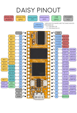
I don’t understand the right side of the card, are all those pins available as digital I/O ?
could you tell me which pin numbers are digital input, and which are digital outputs ?
You should read a bit about STM32 GPIO pins, how they can be configured and which alternative functions are available. You can configure nearly any pin as digital output (31 of them to be exact), only a few pins on Daisy are not available as GPIO (those marked as power or analog audio on pinout).
You can’t make any non-trivial hardware without learning how this microcontroller works and asking questions on forums is not a substitute for learning.
All the pins with blue circles can be used for digital I/O.
Thank you very much for the advises and the clarification, I will read about STM32 GPIO pins.
I’m a max/msp gen user for a long long while and made a huge amount of modules with it, all blocked into the computer, in a way.
I’m a modular user, and would like to integrate those modules/ideas in my workflow.
It seems I can create a 4 bit counter in my patch to clock multiplexers to get lots of pots and switches values to be stored into buffers, a little bit like this patch
and it seems it’s possible.
I’ll still read and see what’s possible, and what’s not.
thank you all for your valuable insights.