Hi everyone,
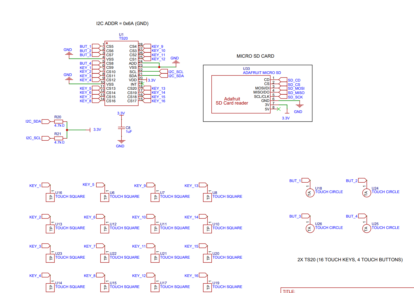
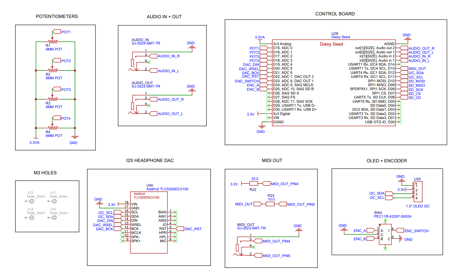
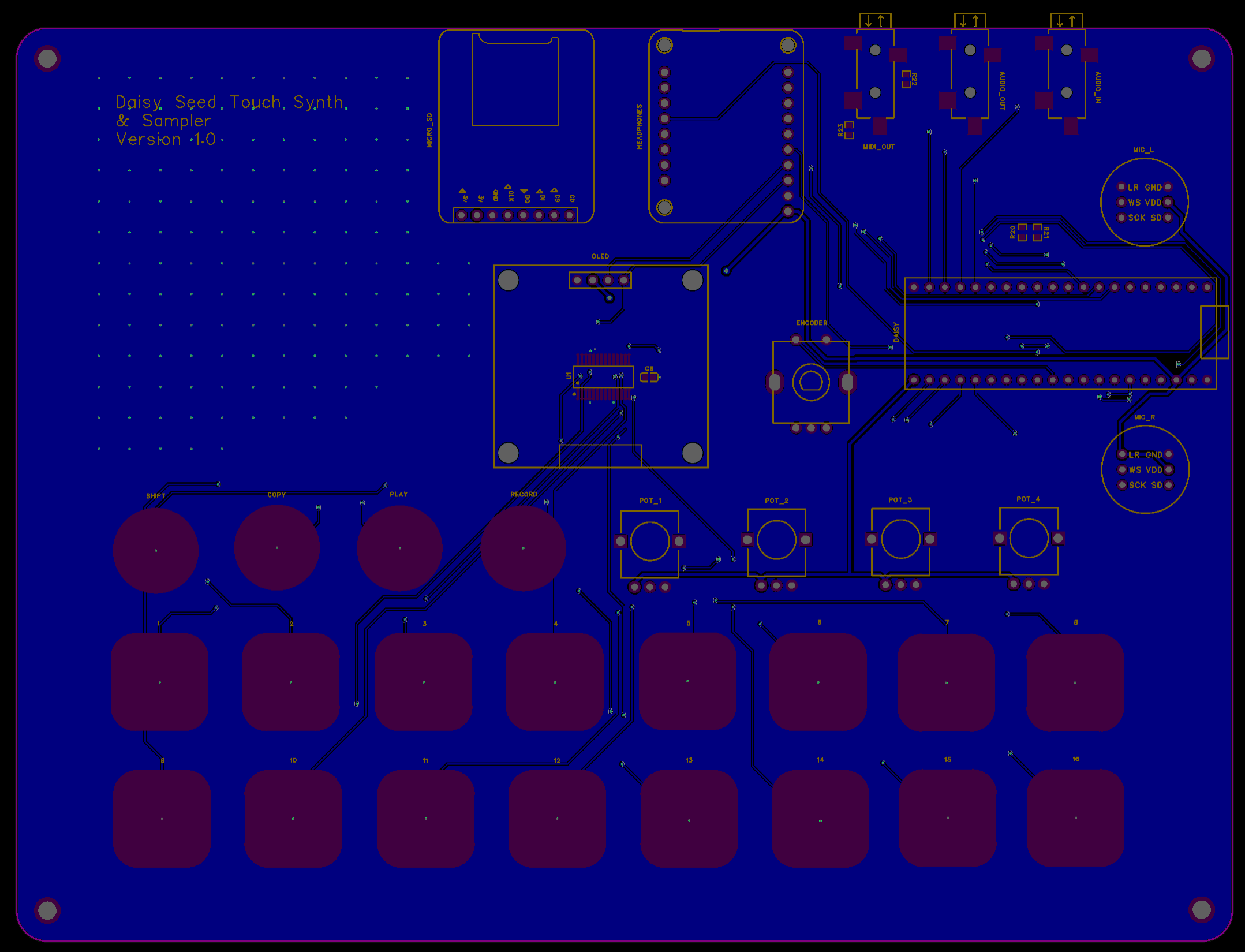
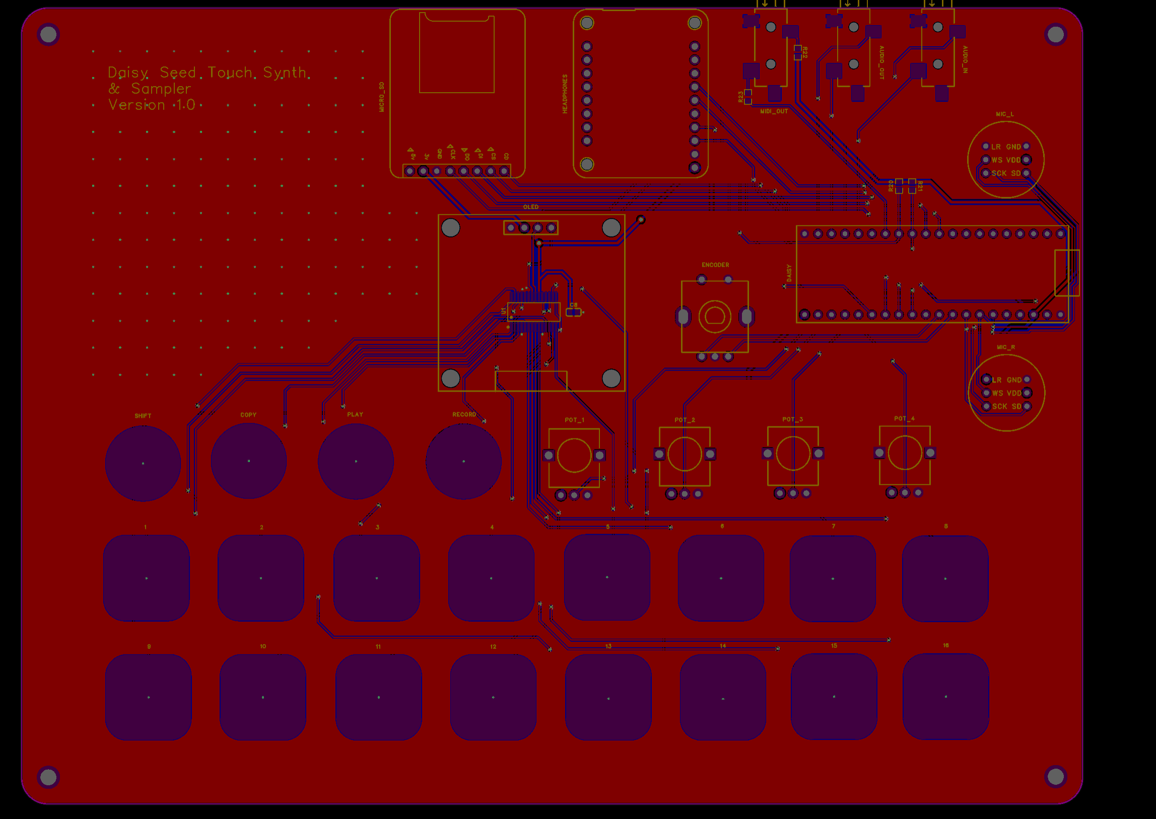
I currently don’t have a multimeter to check if there are any shorts or insufficient power supply for the digital rail but all the components that run on digial logic (I2S MEM mics, Adafruit’s TLV320DAC3100 + MicroSD breakout, SH1106 OLED) did power up when I worked on the breadboard prototype. Only the encoder, potentiometers (analog rail seems to be working fine), and audio jacks are functional (I2S wiring for the DAC + mics are incorrect in the old schematic but have since been assigned to the SAI2 pins). It may be due to faulty wiring for the PCB but I’m not entirely sure. I’ve attached the schematic + trace layers for reference if anyone can kindly provide feedback on any layout and wiring improvements (I’m working on a second iteration that I’d like to release as an open-source project). I have the TS20 touch IC, OLED, and I2S DAC all sharing the same I2C bus but the 3.3V trace goes through both pull-up resistors for the TS20 to the 33 ohm resistor for the MIDI out. Inserting the right microphone breakout to the header sockets in the PCB also seems to shorten the power trace (LED on Daisy Seed shuts off). Would greatly appreciate any help given!