Thanks, Ben. I’ll post the code at the bottom here. Note that I’ve tried USART1 successfully, but 2, 3, 4 produce no output.
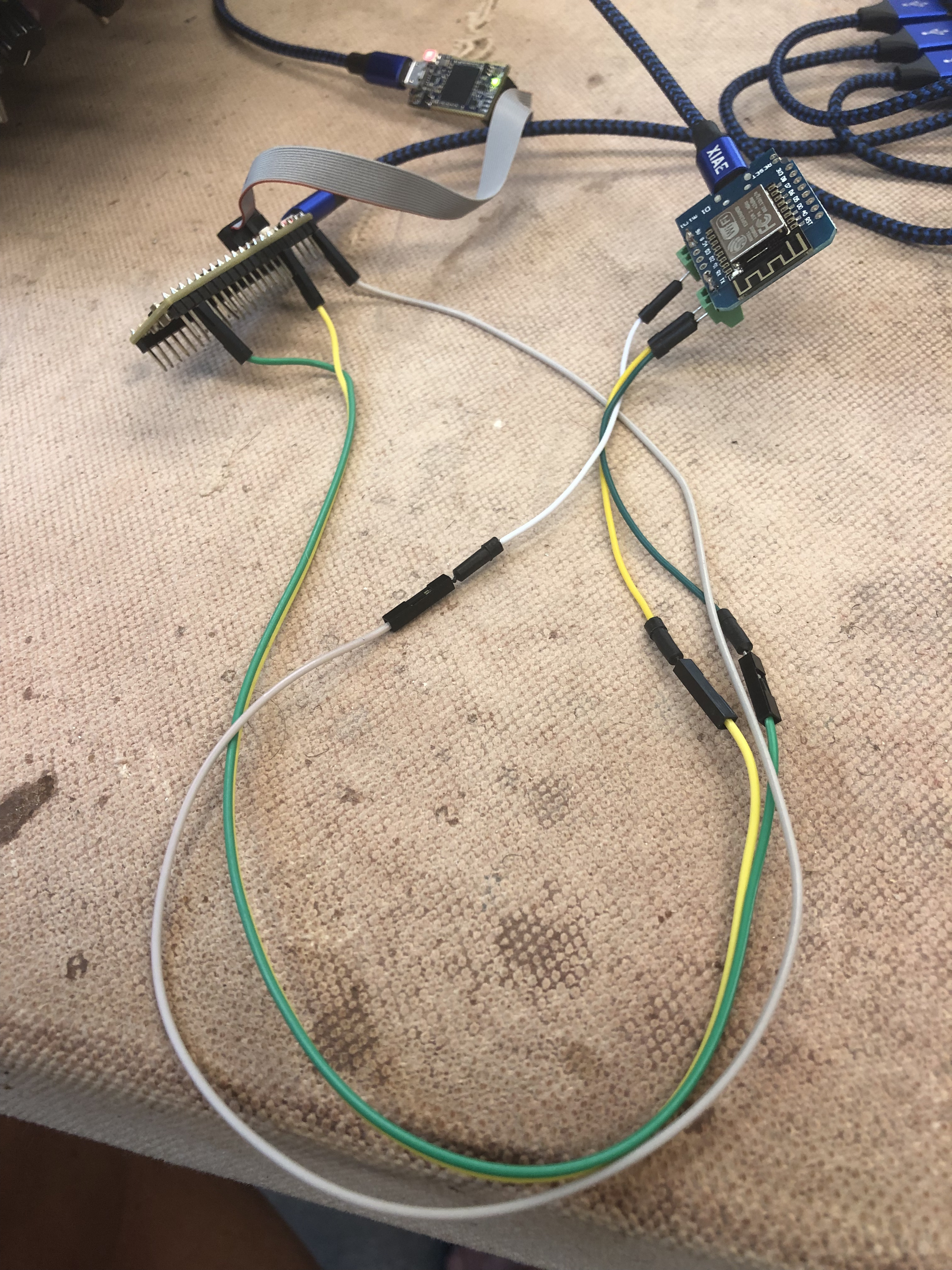
The setup is a WeMos D1 mini (ESP8266) as sender, with the RX/TX pins wired directly to the corresponding pins on the Daisy (RX to TX and vice-versa, of course!). GND on the WeMos is connected to DGND on the Daisy. That’s it! I’ve enclosed a photo to show the setup.
It does work in RX mode. In fact, I have code that sends on USART1, USART2, USART3 simultaneously, and I can read from all 3 ports. If I add UART4, however, as soon as I do an Init() on it, 1, 2, and 3 are no longer “live” 
Here’s the code:
#include "daisy_seed.h"

using namespace daisy;

DaisySeed seed;

int main(void)
{
    seed.Configure();
    seed.Init();

    seed.StartLog(false);
    System::Delay(10000);
    seed.PrintLine("Starting Read-test");

    UartHandler         uart;
    UartHandler::Config config;
    config.baudrate = 9600 ;
    //config.periph   = UartHandler::Config::Peripheral::USART_1;
    config.periph   = UartHandler::Config::Peripheral::USART_2;
    //config.periph        = UartHandler::Config::Peripheral::USART_3;
    //config.periph        = UartHandler::Config::Peripheral::UART_4;
    config.stopbits      = UartHandler::Config::StopBits::BITS_1;
    config.parity        = UartHandler::Config::Parity::NONE;
    config.mode          = UartHandler::Config::Mode::TX_RX;
    config.wordlength    = UartHandler::Config::WordLength::BITS_8;
    //config.pin_config.rx = {DSY_GPIOB, 7};  // (USART_1 RX) Daisy pin 15
    //config.pin_config.tx = {DSY_GPIOB, 6};  // (USART_1 TX) Daisy pin 14
    config.pin_config.rx = {DSY_GPIOA, 3};    // (USART_2 RX) Daisy pin 23
    config.pin_config.tx = {DSY_GPIOA, 2};    // (USART_2 TX) Daisy pin 35
    //config.pin_config.rx = {DSY_GPIOC, 11}; // (USART_3 RX) Daisy pin 1
    //config.pin_config.tx = {DSY_GPIOC, 10}; // (USART_3 TX) Daisy pin 2
    //config.pin_config.rx = {DSY_GPIOA, 1};  // (UART_4 RX)  Daisy pin 12  (or 31?   or 2? )
    //config.pin_config.tx = {DSY_GPIOA, 0};  // (UART_4 TX)  Daisy pin 13  (or 32?   or 3? )

    uart.Init(config);
    uart.StartRx();

    // Loop forever
    for(;;)
    {
        while(uart.Readable())
        {
            uint8_t singleByte = uart.PopRx();
            seed.Print("%c", singleByte);
        }

        // In case of UART Error, (particularly
        //  overrun error), UART disables itself.
        // Flush the buff, and restart.
        if(!uart.RxActive())
        {
            seed.PrintLine("UART reset");
            uart.FlushRx();
            uart.StartRx();
        }
    }
}
The output when USART1 lines are activated is:
Daisy is online
===============
Starting Read-test
test
test
test
When USART2, USART3, or UART4 lines are activated, the output is the same, except that no “test” lines appear.
BTW, The ambiguous comments following the UART4 pins in the code are due to my confusion in interpreting the Daisy seed pinout (below). I’d love some guidance as to how to read this data sheet! Thanks.