That depends on how you installed it in the first place? If you used git you’d normally do something like a ‘git pull’.
No result. I write in /libdaisy “git pull”
I got this:
$ git pull
remote: Enumerating objects: 10, done.
remote: Counting objects: 100% (10/10), done.
remote: Compressing objects: 100% (6/6), done.
remote: Total 10 (delta 4), reused 10 (delta 4), pack-reused 0
Unpacking objects: 100% (10/10), 6.86 KiB | 73.00 KiB/s, done.
From GitHub - electro-smith/libDaisy: Hardware Library for the Daisy Audio Platform
-
[new branch] dual_codec_fix → origin/dual_codec_fix
You are not currently on a branch.
Please specify which branch you want to merge with.
See git-pull(1) for details.git pull
But in the end, the errors are all in place. Nothing has changed
thanks a lot! I run “make” inside the libdaisy dir and things seem to have changed, but I think I’m still doing something wrong. I now get the following message when trying to program the patch.Init():
dfu-util: Warning: Invalid DFU suffix signature
dfu-util: A valid DFU suffix will be required in a future dfu-util release
Opening DFU capable USB device...
Device ID 0483:df11
Device DFU version 011a
Claiming USB DFU Interface...
Setting Alternate Interface #0 ...
Determining device status...
DFU state(2) = dfuIDLE, status(0) = No error condition is present
DFU mode device DFU version 011a
Device returned transfer size 1024
DfuSe interface name: "Internal Flash   "
Downloading element to address = 0x08000000, size = 79480
Erase   	[=========================] 100%        79480 bytes
Erase    done.
Download	[=========================] 100%        79480 bytes
Download done.
File downloaded successfully
Submitting leave request...
dfu-util: Error during download get_status
make: *** [program-dfu] Error 74
I also run " git pull --recurse-submodules" inside DaisyExamples directory and “git checkout master” and “git pull origin master” inside libdaisy to see if everything is up to date and all looks good.
The module is actually somehow programmed but it does not respond to any knob if turned. I’m uploading the patch_init_test.pd patch, and according to that, the led brightness should change when turning CV_2 knob, but nothing happens, the led stays on. I then tried to upload a super simple “beep” program patching and osc~ into the dac~ and I can hear some sound coming out of the module, but it’s very noisy a low in volume.
That final dfu-util error is actually to be expected. You have successfully flashed your Daisy!
Dumb error, I had the module connected only via USB and the ribbon cable was not inserted! thanks a lot! Have a great day!
Try “git checkout master”, then “git pull”, then “make”.
Then go back to the pd2dsy folder and try building.
Another day, another problem ![]()
I tried to program my patch.Init() with more complex pd patches but seemed like some objects were not recognized or parsed correctly. I got error messages like
Error pd2hv: [value] in "OSC_patch_init.pd/expr~.pd/[value]" @ (x:411, y:74): Don't know how to parse object "expr". Is it an object supported by Heavy? Is it an abstraction? Have the search paths been correctly configured?
I had the same problem with other objects like vline~; I managed to partially solve the problem by copying all the objects from pd2hv/libs/pd to my pd2dsy folder (messy but working). I then tried to upload my patch and most of the error messages were gone except for those regarding expr~ and, as a matter of fact, looking into the pd2hc/libs/pd folder, expr~.pd is not there!
Does anyone know where to find it? I’ve been looking for a while but I seem not to find it anywhere.
Tried to upload a patch that don’t use the expr~ object and everything went fine, so, I guess the expr~.pd file is my only and hopefully last problem!
While I don’t know if this is the exact fork of hvcc that is being used here, I did find these useful bits of documentation about which objects are and aren’t supported:
hvcc/09.supported_vanilla_objects.md at master-bela · giuliomoro/hvcc (github.com)
hvcc/10.unsupported_vanilla_objects.md at master-bela · giuliomoro/hvcc (github.com)
Unfortunately it looks like expr~ shows up in the unsupported list.
Cheers
pd2daisy requirements.txt “es-hvcc-sensors==0.2.1” point to es-hvcc-sensors · PyPI
hvcc/docs/09.supported_vanilla_objects.md at develop · CorvusPrudens/hvcc · GitHub
hvcc/docs/10.unsupported_vanilla_objects.md at develop · CorvusPrudens/hvcc · GitHub
its alive!!! THANK YOU!
It’s a temporary fork of hvcc | The heavy hvcc compiler for Pure Data patches. Updated to python3 and additional generators
Somebody is working on [expr] and [expr~] objects as we speak, but it will need some more work and a lot of testing before it will be generally available.
Hi,
I have finaly mi Daisy Pod playing PD patches.
Could I have several patches on Daisy and switch between them? If it is possible, how could I do that?
Thanks
I have a patch working great with controls on my POD, but know I would like to go deeper with my other plain Daisy Seed board and try to use the GPIOs, but reading information and checking examples I have not clear how to acces to them. My question is:
I can see in the pinout schematic 12 Analogic GPIO and I wold like to use them for use some pots, for example. If I open the pd2daisy example named seed_test.ped i can see that it recieves from for example from “r ChannelA @hv_param 0 1 0.5”. Is this the first GPIO? Channel means Gpio.
Please, I really appreciate if someone couls shed some ligth on this.
Thanks in advance
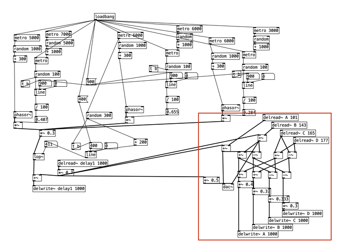
Another question. I am trying to run this pd patch. If I remove the red area and connect directly to output no problem, but when I use this reverb chain Daisy Pod just swich on both led white ligth and play a stable pitch.
I was checking HVCC vanilla allowed objects and I guess it is not using any of them.
Any idea about with one could be the problem?
Hello everyone!
I’m facing a really strange problem. The left audio output of my patch.Init() doesn’t work anymore with pure data patches. Has anyone experienced this problem?
If I upload some example codes from the Daisy Web Programmer everything works fine: I tried some Oscillator examples and I have a really good audio output from both channels, but as soon as I upload a Pd patch, the left channel is silent.
I tried to upload the patch_init_test.pd file from the pd2dsy examples to actually see if this was just a fault of mine, and still no audio on the left channel (the patch_init_test.pd file was actually the very first pd patch I tried to upload when I first installed all the pd2dsy files, and it used to work great!). I know that in this examples the left channel is only triggered when gate_in_1 is triggered, but nothing happens and the gate_in_1 works fine!
Thanks to anyone who can help! ![]()
Hello!
Really enjoying being able to integrate PD into my Seed. I do wish I could get some reverb going though. I have 2 seeds so I wouldn’t object to using one only for FX while the other is a synth. But I can’t get any of the PD Vanilla Objects or freeverb to work. Delay works fine although it seems a little heavy at times.
I saw a YouTube review where the guy makes a sort of sliding synth with a ribbon potentiometer and programs it in Arduino IDE. His had reverb but it was coded in. Is it possible to stack code from, say, Arduino IDE and a PD patch?
I appreciate any support as well as the support I’ve already received!
I started on my Patch.Init() today. I have to say that installing the tools was very smooth. I have audio passing and can get knob input. I am new to pd but do know some max/msp.
I have some questions about this patch:
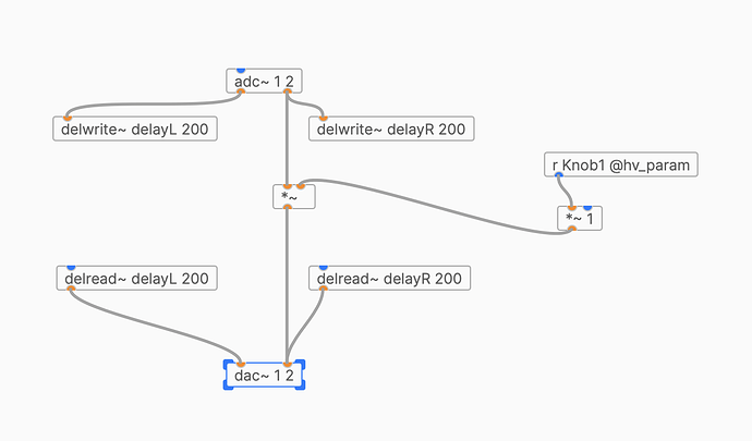
I can’t get my delay to work. It has no effect on the audio at all. What am I doing wrong? It seems to be passing audio straight through with zero delay.
I tried to add a [loadbang] → [200] → [delread~] to init the delay time but it had no effect.
Also wondering why when I turn up the knob it seems to make the audio louder than unity.
Oh yeah, and how do I get some debug output? Would love to be able to see the value of a number message, for example.
You will need to create a feedback.
Here is a functional variable delay patch with two controls:

Debug output is currently not possible (was also looking for a way to do this the other day. printing to uart console for instance).
Per @dreamer 's suggestion, I’m coming here from the plugdata Discord to discuss this:
I’m trying to build an abstraction that will give PWM output on pins, thereby enabling not only the cool sounds of PWM audio on additional pins, but also LED and servo control.
LED brightness seems easy. I’m not worried about that.
What I’m trying to solve is that servos require a pulse width of approximately 1 to 2ms. As I understand it, that’s precisely one sample block, which means that we can’t use control signal to control a servo except as a binary position.
Is there a way to adjust the block size, either dynamically in a patch, or as part of a board description? Ideally, I’d like to get 180x the number of steps that I can get right now.
(As far as I can tell, this limitation comes from the assumption that digital out pins are changed at Control Rate. If they were Signal Rate objects, I’d be finding some completely different way of frustrating myself.)

