My cat broke off USB connector on Daisy Seed

USB cable was plugged in overnight and the cat decided that my project was a good place to sleep and leaned so hard against the upright cable that it broke the connector off of the circuit board. No way am I going get a soldering iron near those microscopic pads without destroying the device so I was wondering if I could use physical pins 1, 36, 37, ground, (and 3.3v?) to load programs or do I need to invest in a ST-Link and an adapter cable?

1 Like

Ouch! Feeling for you. If you go the ST Link route, this is what works for us:

https://www.mouser.de/ProductDetail/STMicroelectronics/ST-LINK-V2?qs=H4BOwPtf9MC1sDQ8j3cy4w==

https://www.mouser.de/ProductDetail/Olimex-Ltd/ARM-JTAG-20-10?qs=DUTFWDROaMbVQp3WoAdijQ%3D%3D

Thanks for the links to the hardware. Unfortunately the cost after adding tax and shipping equals the price for a new Daisy Seed. I don’t think I can justify the ST Link route and will probably order another Daisy if I can’t use alternate pinning.

Oh no! Your poor Daisy!

A cheaper JTAG solution is the stlink v3 mini. It does have extra slots on the header, but if you center it on the connector it works great. I’ve been using one for a little over a week now.

It doesn’t require the secondary adapter either. Someone more local than mouser might sell this with cheaper shipping as well.

Maybe this would help.

Maybe I should pay a little more attention to kitty :cat2: before it’s too late! :cat:
:grinning:

Mouser had the best price around so I pulled the trigger for one. After tax and shipping the total was just under $20 (usd). It should arrive by the middle of next week. Hopefully the investment will benefit my attempt to switch from Arduino to Visual Studio after I complete my current project. Btw, any estimated time for making dynamic memory available in Arduino?

So…

MOUSEr helped you sort out your kitty situation?

Almost like an episode om Tom and Jerry, but reversed :crazy_face: :stuck_out_tongue_winking_eye:

Haha, yah. This kludge… err project of mine is starting to make me feel a bit like Wilie E Coyote. :smiley:dba

1 Like

Been there… and still am, haha :slight_smile:

Hi, I’ve ordered a STLink clone. The 5x2 connector is labelled as JTAG on the schematic but hope it will do SWD as per this:

Screenshot 2020-07-27 at 18.15.20

Could you elaborate on how to connect the STLINK-V3MINI to the Daisy Seed or possibly post a picture? Am I assuming correctly that I need to power the Daisy via Vin while flashing the program since the cat decided that I didn’t need a USB? Can I use this method to flash the program from the Arduino IDE or is it time to step up to Visual Studio (or VSCODE)?

@TGargasz , while you didn’t ask me, I’ll note that this is already explained in wiki, see “Hardware Requirements”. And SWDIO interface provides 3.3V to MCU during flashing, you don’t need to power it by anything else. Also, comparing Arduino IDE to VScode is like comparing Arduino MCU performance to Daisy.

I’m sorry for the confusion. I should have tagged #shensley. He mentioned he was using STLINK-V3MINI which has a 2x14 mini header and does not adhere to the wiki instructions. Thank you for letting me know that the STLINK will power the Daisy Seed while flashing. I wasn’t attempting to compare Arduino with VSCode. My question was asking if I needed to change my programming IDE in order to use the STLINK to flash the Daisy Seed.

With ST-link mini you should center headers (so 2 pins on the left and on the right edge would be unused) and use the same orientation as wiki describe (align mark on module and red line on programmer cable).

VSCode is not what actually flashes your device - this is done by openocd. And you would use gdb for debugging with whatever IDE you’ll end up using. It doesn’t have to be specifically vscode, it’s just that it’s got a very good plugin for debugging on ARM.

Just in case anyone else decides to (or is forced to) abandon flashing their programs through the USB connector on the Daisy Seed and use a STLINK V3 MINI, here’s some information that may help.

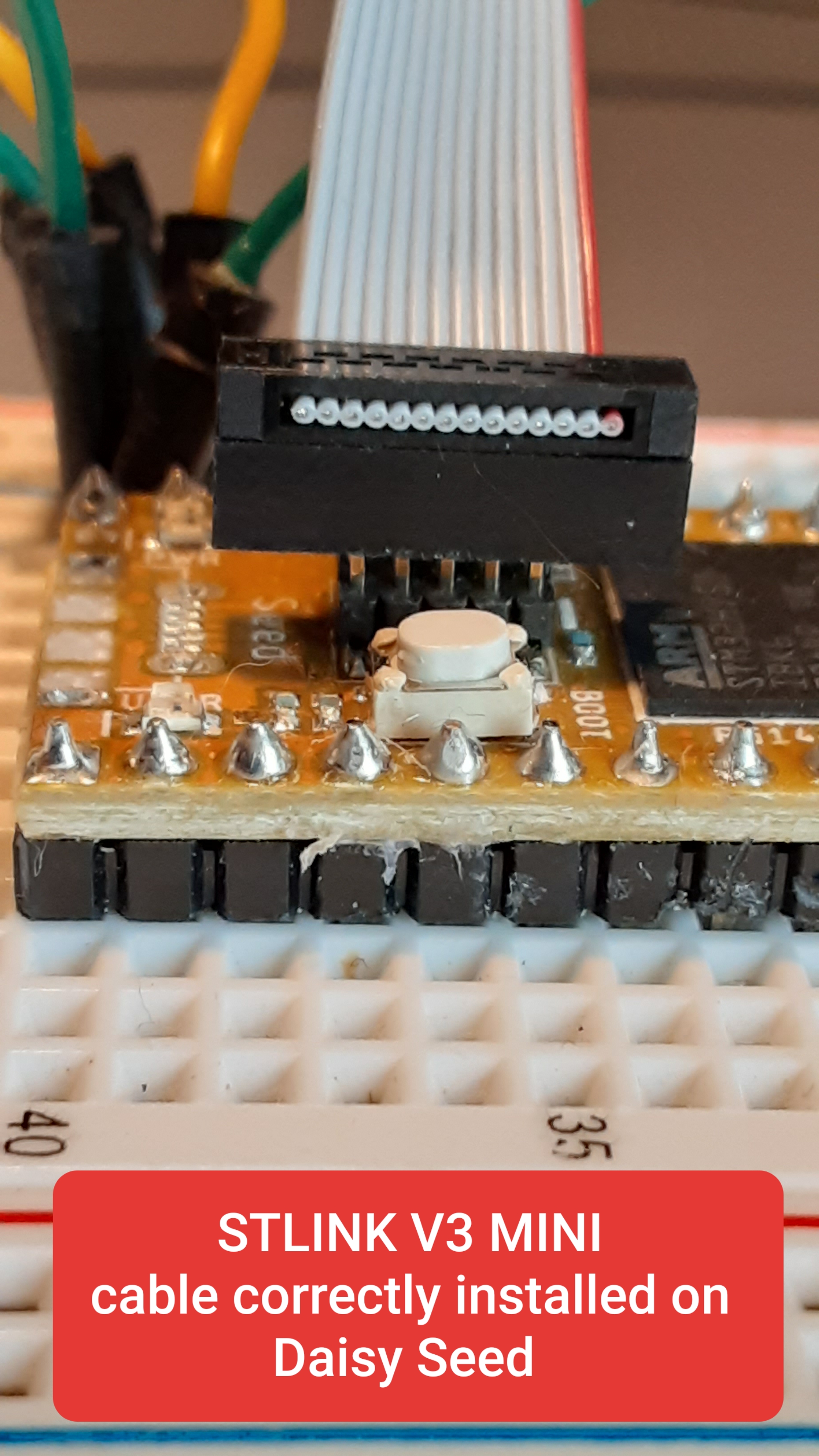
  1. The v3 mini comes with a 14 pin connector cable that must be centered on the 10 pin Daisy header.
  2. The cable must be oriented so that the wire with the red stripe is closest to the ARM chip.
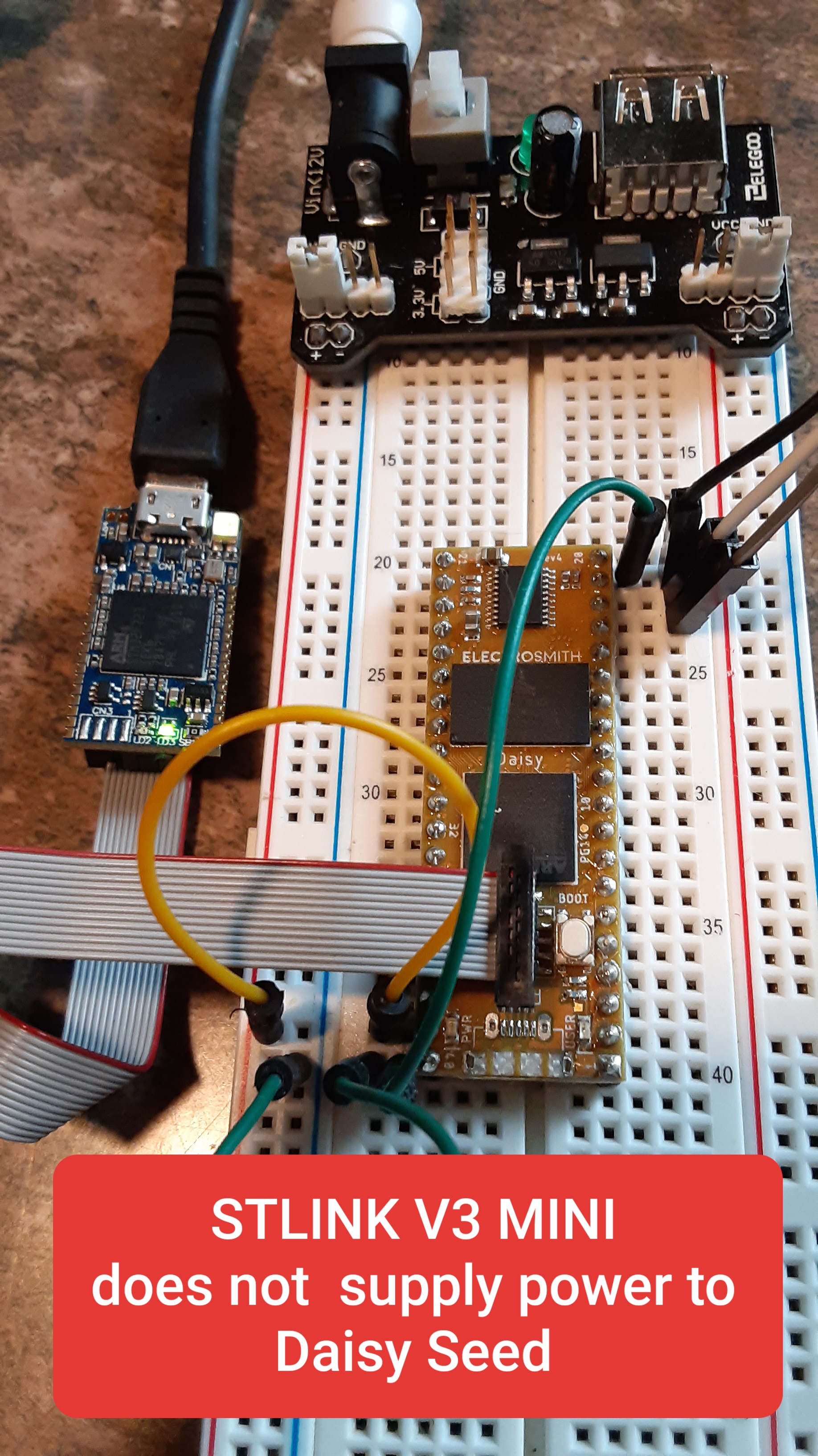
  3. The v3 mini does not supply power to the Daisy. You must supply power either through the USB port or by Vin (physical pin 39).

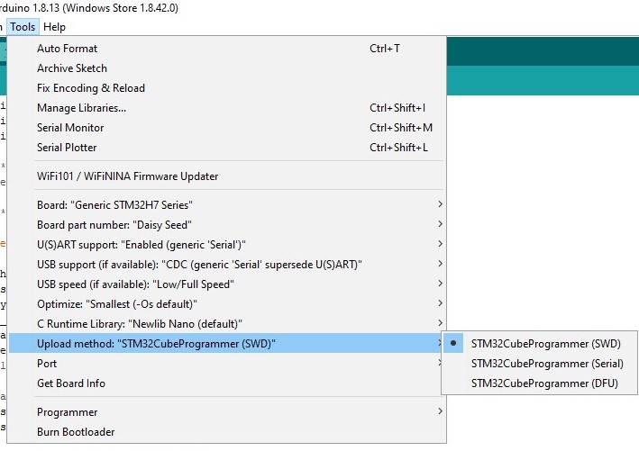
If you’re using Arduino IDE

  1. You don’t need to install any additional software on top of what is already required to use the USB port for loading your program to the Daisy.
  2. You need to change Upload Method from DFU to SWD (see attached screen shot).

I hope this lowers somebody’s learning curve or frustration factor. :slightly_smiling_face:

9 Likes