since we’ve discussed it before a bit, I can add some more hints related ILI9341 usage:
it’s possible to switch DMA to transfer data in 16 bit words instead of 8 bit, this cuts number of DMA transactions in half and could make things slightly faster
it’s not mandatory to use D1 RAM for DMA buffers, i.e. I’ve placed it to D2. this is important because D1 is the largest section of fast internal SRAM and you may find better use for it.
ok, i figured it out
it wasn’t easy for me ( not a cpp guy) , one has to understand the mapping of the physical pins to the list dsy_gpio_pin in daisy_seed.cpp.
Cheers!
Oh right, it’s already there (I was experimenting with different sections locations before and haven’t realized that this is how libDaisy uses it already).
So regarding DMA transfers, you have to change peripherals configuration (both hardware registers and HAL object) before and after transfer, something like this:
OLED_SPIInst->Instance->CFG1 |= SPI_CFG1_DSIZE_3;
OLED_SPIInst->Init.DataSize = SPI_DATASIZE_16BIT;
HAL_SPI_Transmit_DMA(OLED_SPIInst, buf, size); // Size value is in 16 bit words now

// DMA TX callback
void HAL_SPI_TxCpltCallback(SPI_HandleTypeDef* hspi) {
    if (hspi == OLED_SPIInst) {
        // 8 bit transfer
        OLED_SPIInst->Instance->CFG1 &= ~SPI_CFG1_DSIZE_3;
        OLED_SPIInst->Init.DataSize = SPI_DATASIZE_8BIT;
    }
}
You have to return to 8 bits after you’re done with DMA, because commands won’t work in this mode. At least I couldn’t get them to work.
I had some extra code for changing LSB/MSB direction on this peripheral when using it with ILI9341, but I recall that it was needed even without DMA. So I’m not posting it here, I think it won’t be necessary if you haven’t used it before.
What do you think about my approach of sending screen buffer in 3 chunks? I can’t really recall why I end up with 3 chunks, but it gave some meaningful FPS improvement comparing to other divisions (I slightly recalling that I wasn’t able to transfer the whole buffer at once due to buffer limitation)
If you divide it by 2 you end up transmitting the same amount of data (in bytes). So the idea here is not to divide by 2 and transmit twice as much.
That’s exactly the issue that 16 bit mode improves. You can’t send more than 64k data in 8 bit mode because transmission size length is limited by 16 bits (65535 is max value) . Buffer size is 320 * 240 * 2 (16 bit color), so you need 2.3 transmissions. You would have to use 3 transfers, but if you use 16 bit SPI mode you can do it in just 2 since that 16 bit DMA counter counts in 16 bit words instead 8 bit bytes in such case.
I can not really wrap my head around it. So bear with me.
Currently I’m sending 3 identically sized chunks (uint16_t buf_chunk_size = 51200;). It seems I’ll get out of bounds of the buffer, when DMA would try to transfer the second chunk. Should I update the above to ( 320 * 240 * 2 ) / 2?
(I don’t have access to the hardware, so can’t really test myself )
There are 2 variables to determine total transfer time for sending your buffer:
amount of data to be transferred, this depends only on buffer size used for display and you can’t decrease this (but you can send it faster with higher SPI clock)
number of transfers (because hardware needs some time to start/end each DMA transfer, there also arbitration for DMA streams used by different peripherals, etc). this is the part that we can decrease if we transfer larger amount at once.
We’re limited by 64k counter for DMA transfer size, but the important part is that it’s using bytes or double byte words depending on SPI mode used. So we can double transfer size if SPI mode is set to 16 bit.
If you were to use 16 bit SPI mode, you could use 51200 for first transaction as before (sending 102400 bytes this time) and 25600 for the second one to send remaining data. Or you could use 38400 for both of them to keep their sizes equal, this seems more reasonable.
I am going to start work on brining up the PCAL9555APW,118 device. Any thoughts or ideas before I start? I was going to look a the led driver as it uses an NXP part that looks similar in how I might setup the device.
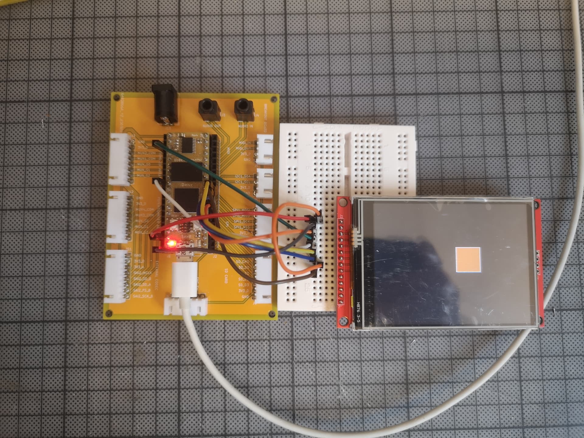
I was wondering if anyone had got this code for the ILI9341 TFT screen to work? I’ve got it all wired up correctly and I’ve compiled and loaded the code but all I get is a white screen, with a flicker when the code is loaded. The guy who wrote is doesn’t appear to have been on this forum for a while so I’ll assume he’s not around, but has anyone else tried it and got it working?
Hi, thanks for replying. To confirm, this is the latest code? daisy_ ILI9341.hpp · GitHub
I had to change the name of daisy_ ILI9341.hpp to match the #include "ili9341_ui_driver.hpp" in ili9341_ui_driver.cpp, and also because I’m using a seed I removed any pod references, but it built and loaded fine. I’m using Rev4 by the way.
It’s definitely not the latest code, but it is fully functional with a caveat regarding caching. You’d need to increase the non-cachable region to make DMA transfers properly flush the whole buffer to the screen. To do so, you’d need to change libdaisy/src/sys/system.cpp:528 to MPU_InitStruct.Size = MPU_REGION_SIZE_256KB;
In lines 73/74 of daisy_ILI9341.hpp (the name of which I changed to ili9341_ui_driver.hpp to match the #include statment in the other file) to match what was specified in the pin mappings at the top:
uint8_t dc_pin = 22;
uint8_t reset_pin = 16;
And that got it working. It seems to be commented v0.1 mix up so I assume this is known about. Anyway, all working now.
Thank you for your work on this, you’ve saved me a huge amount of time by the look of it!